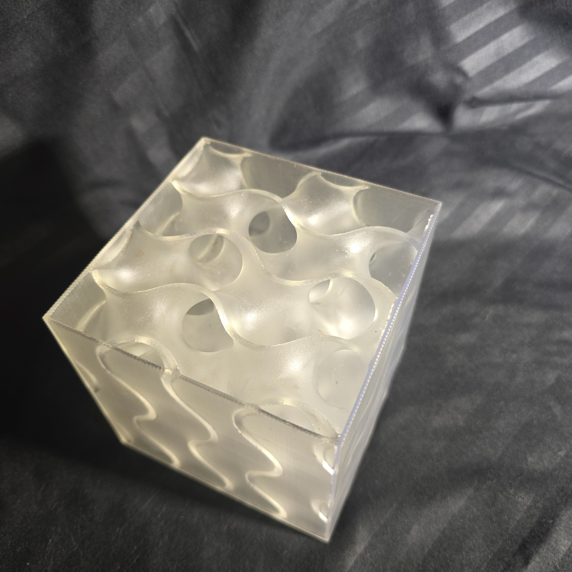
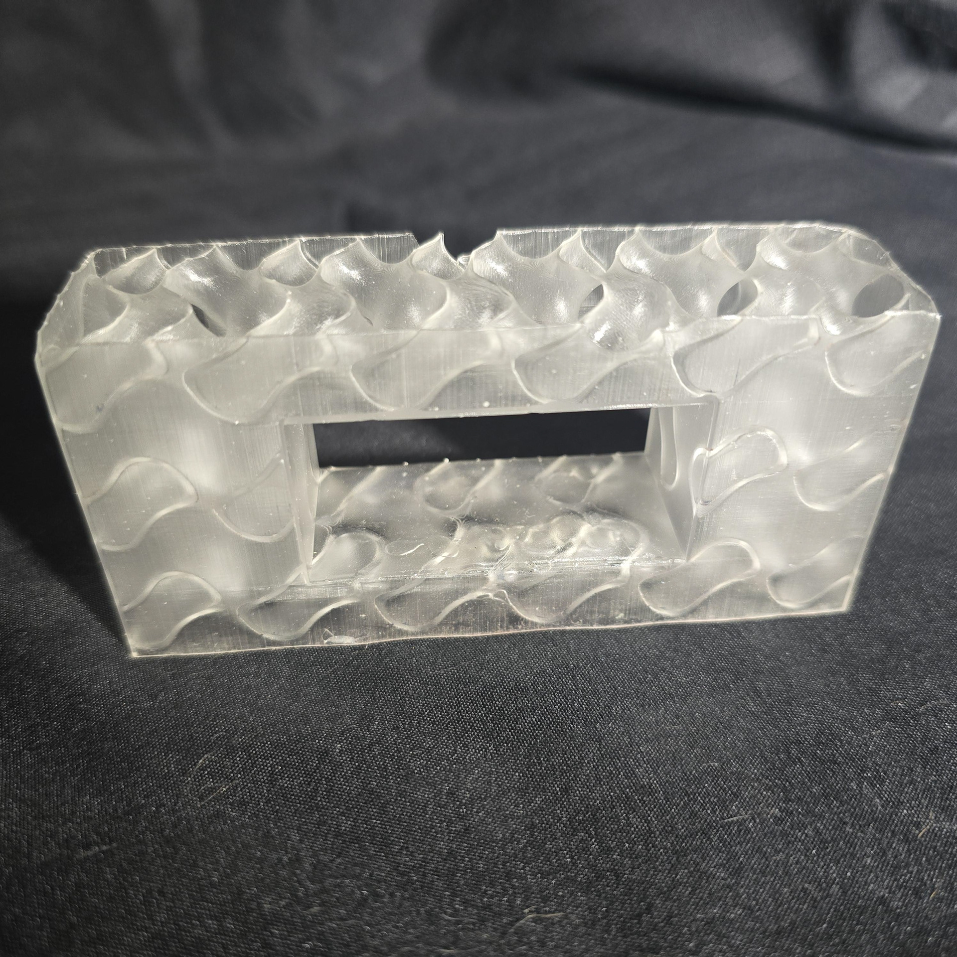
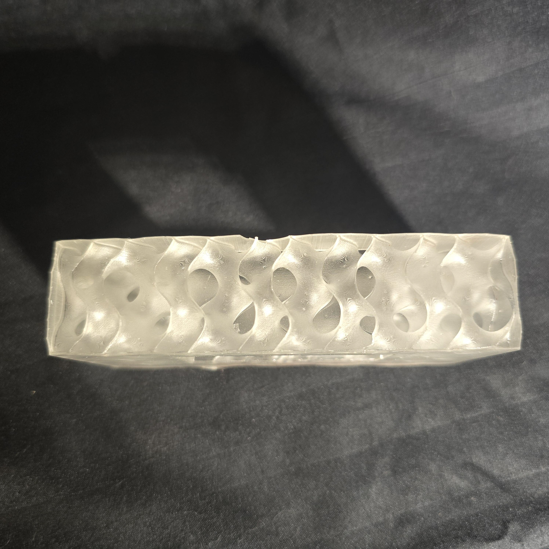
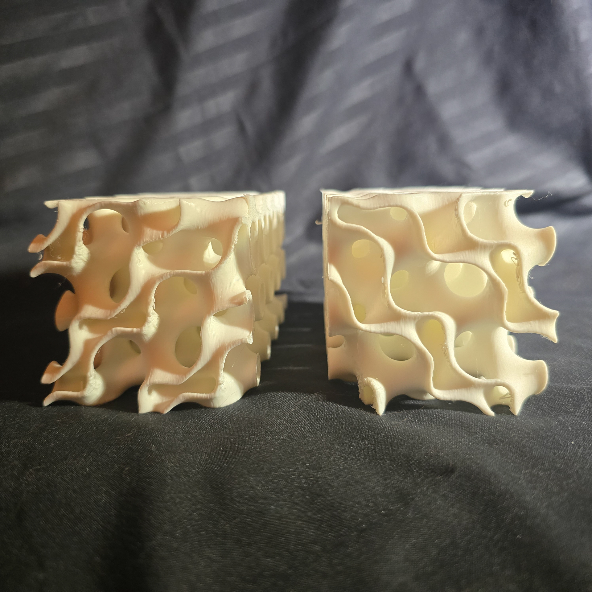
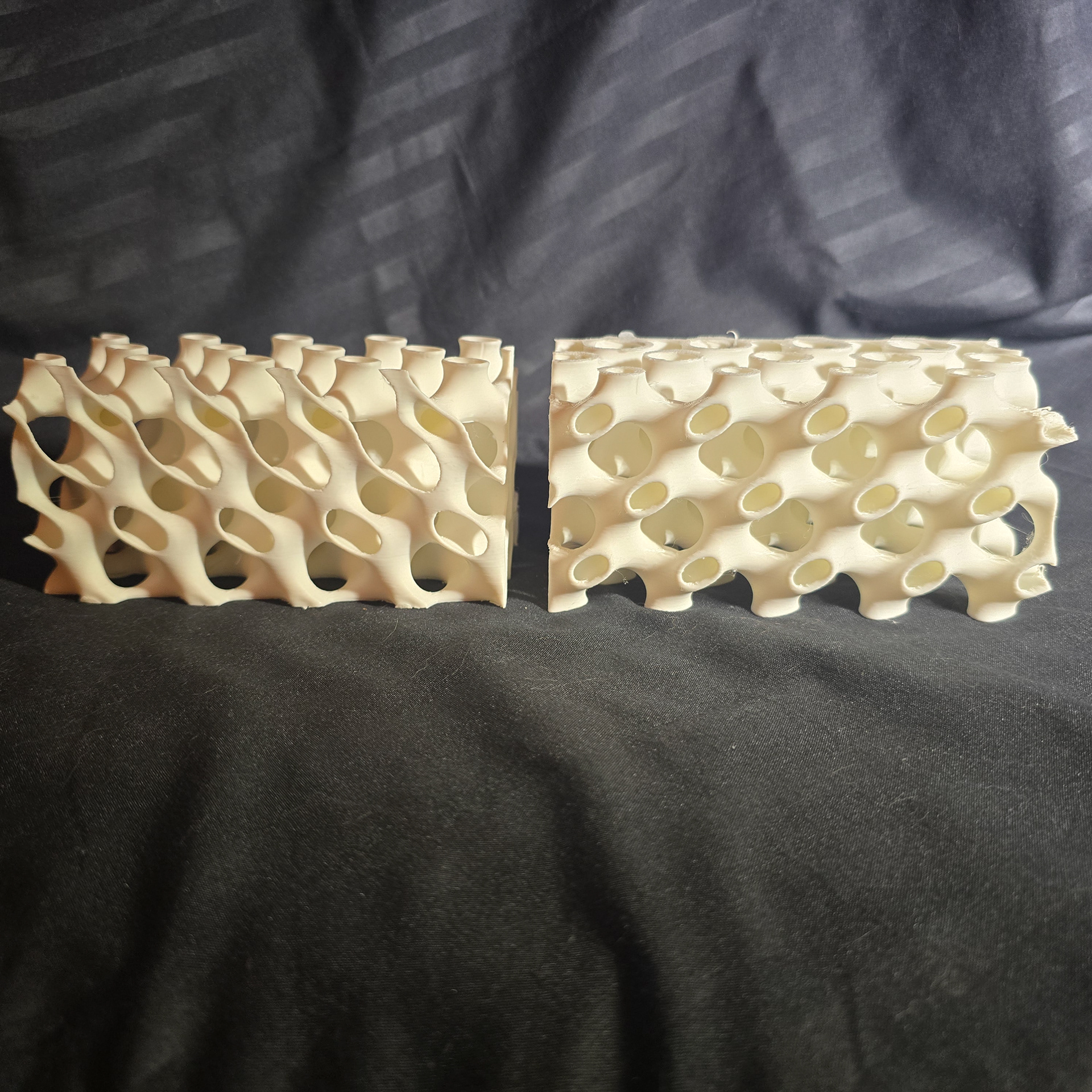
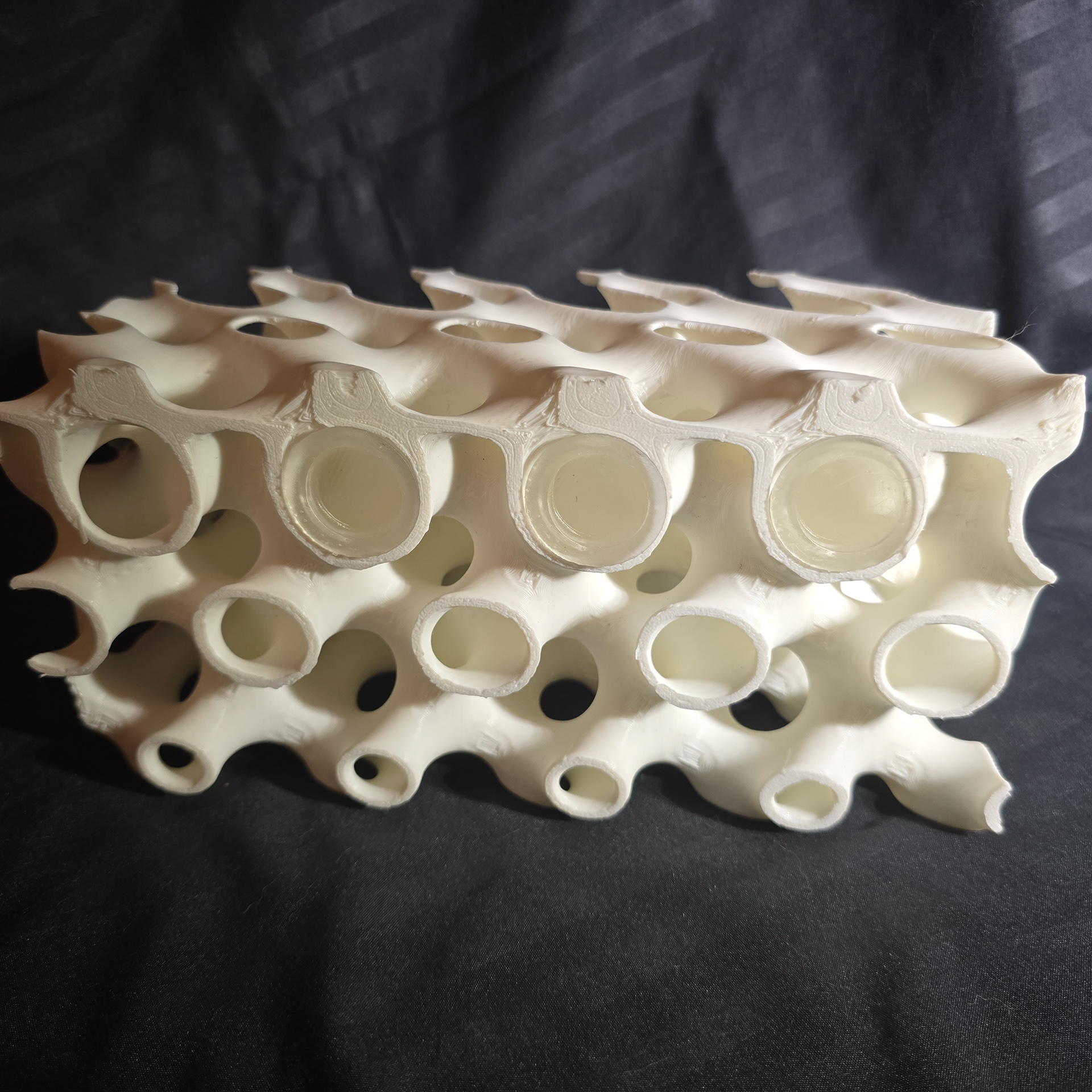
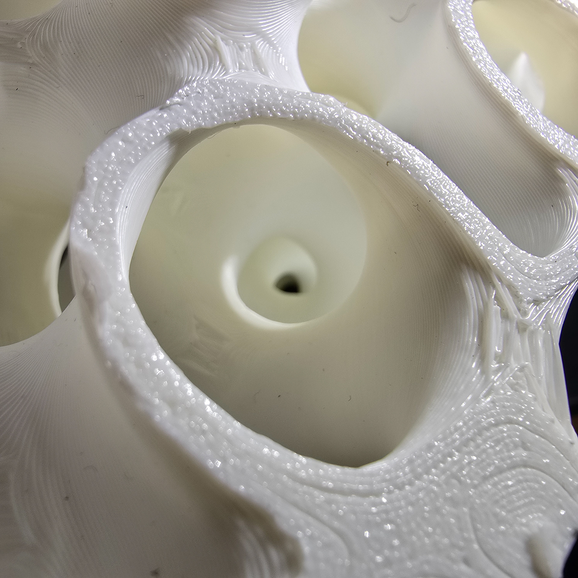
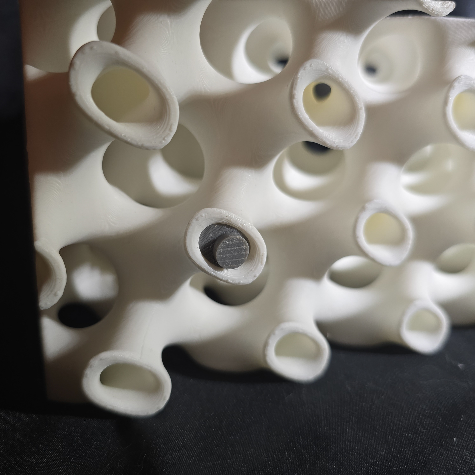
These are the initial 100mm tests with the gyroid fields in PLA printing and resin. Both of these, along with all other gyroids here, are printable without any supports. The white PLA is a negative of the gyroid field which creates more tubular channels compared to the surfaces of the normal field
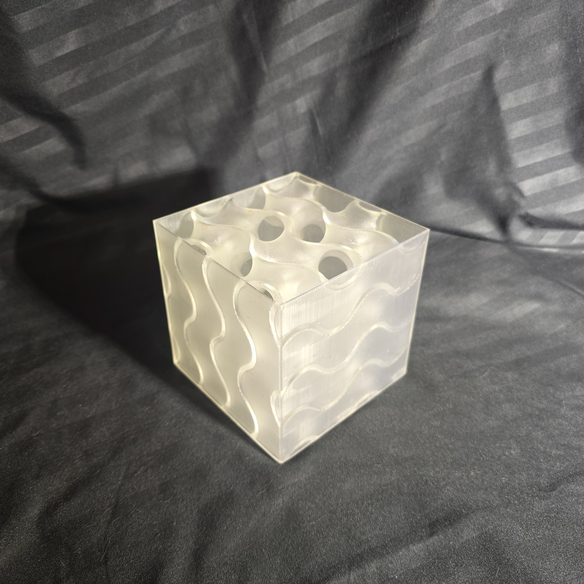
Enclosed cubic resin print exterior
Showing the open top
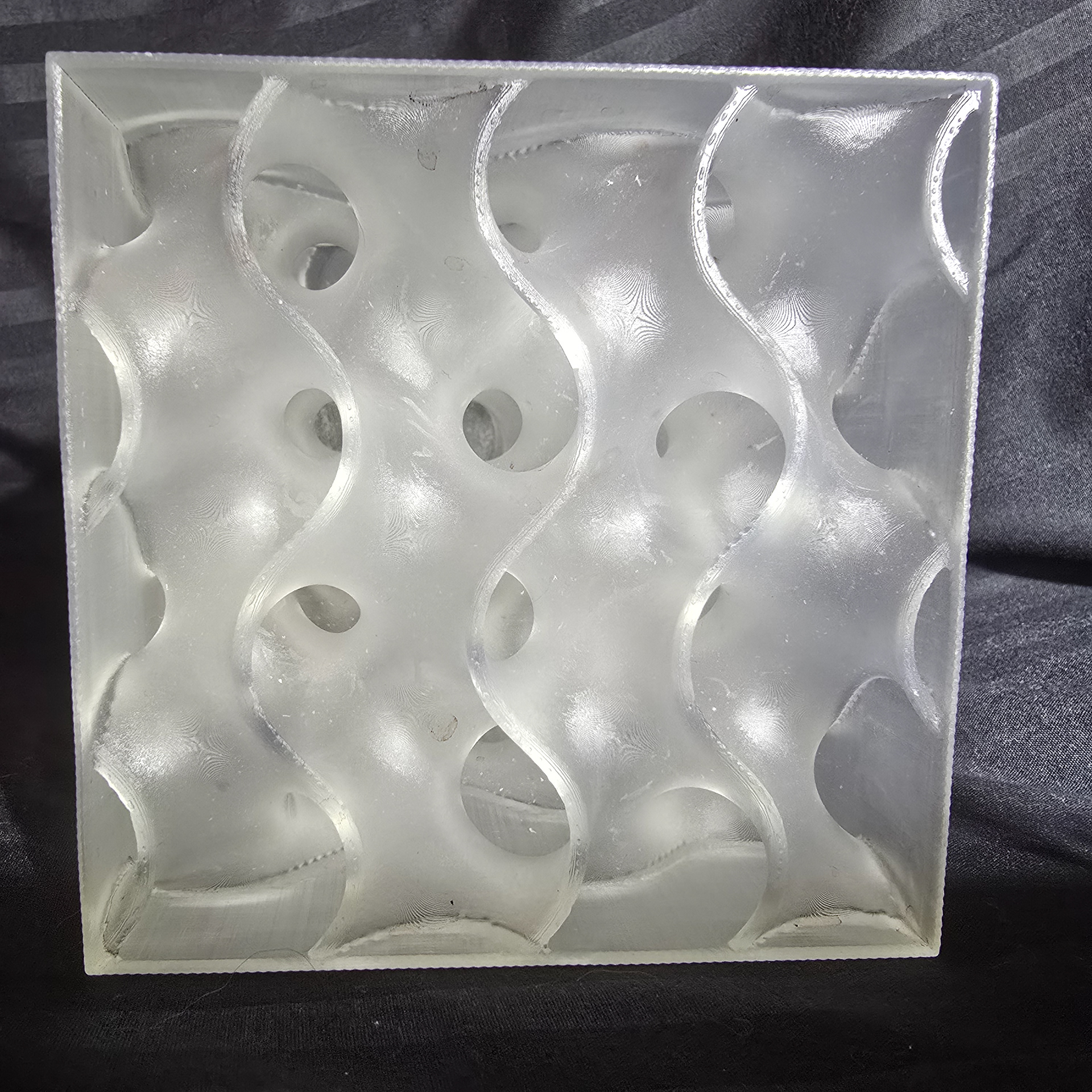
View into interior
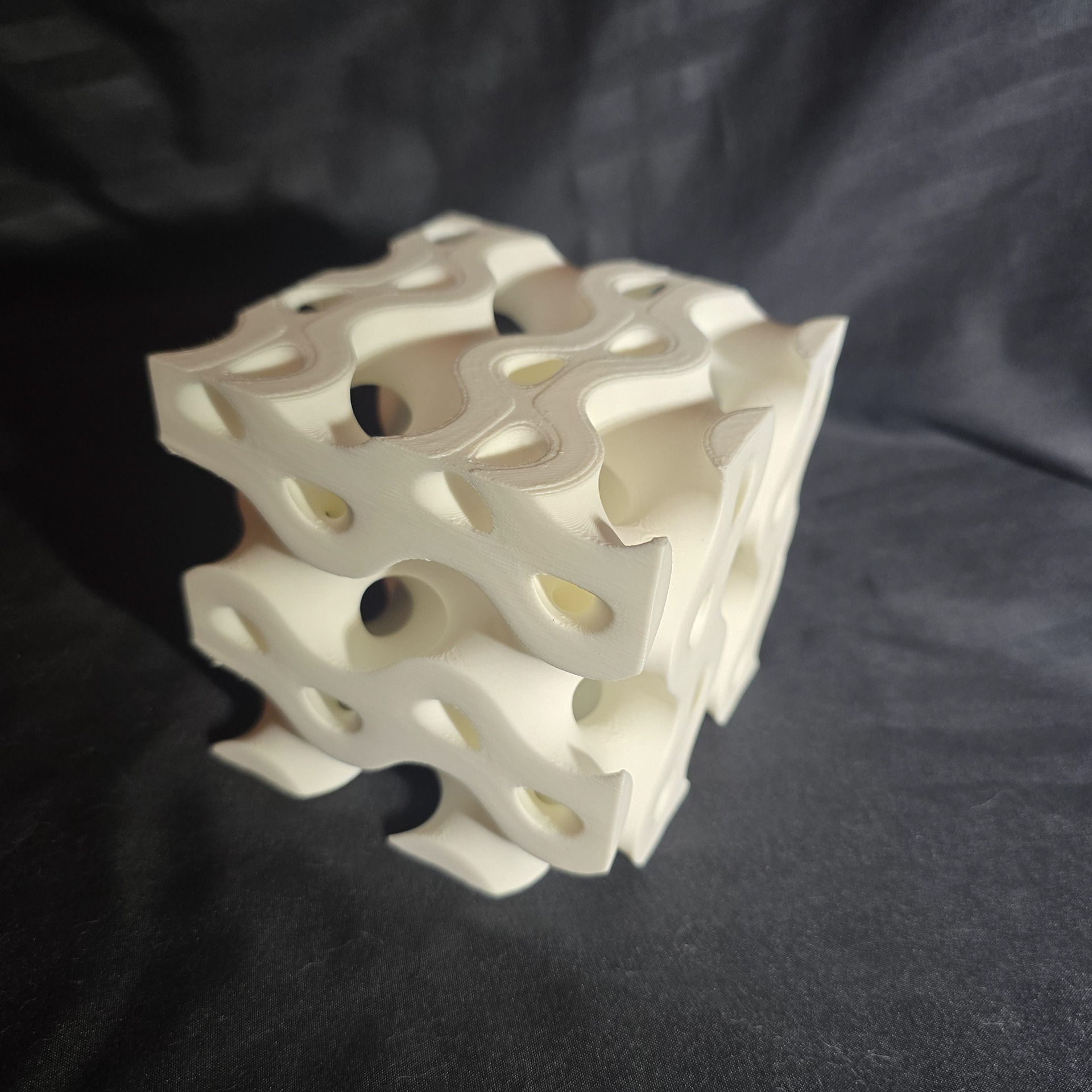
Open 100mm cubicFDM print exterior
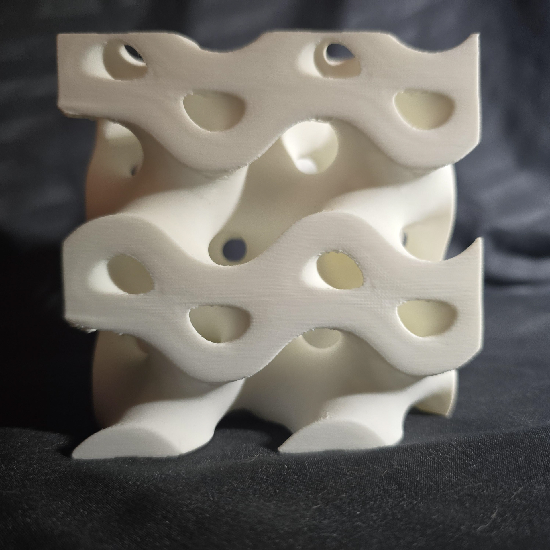
More channel structure than positive field
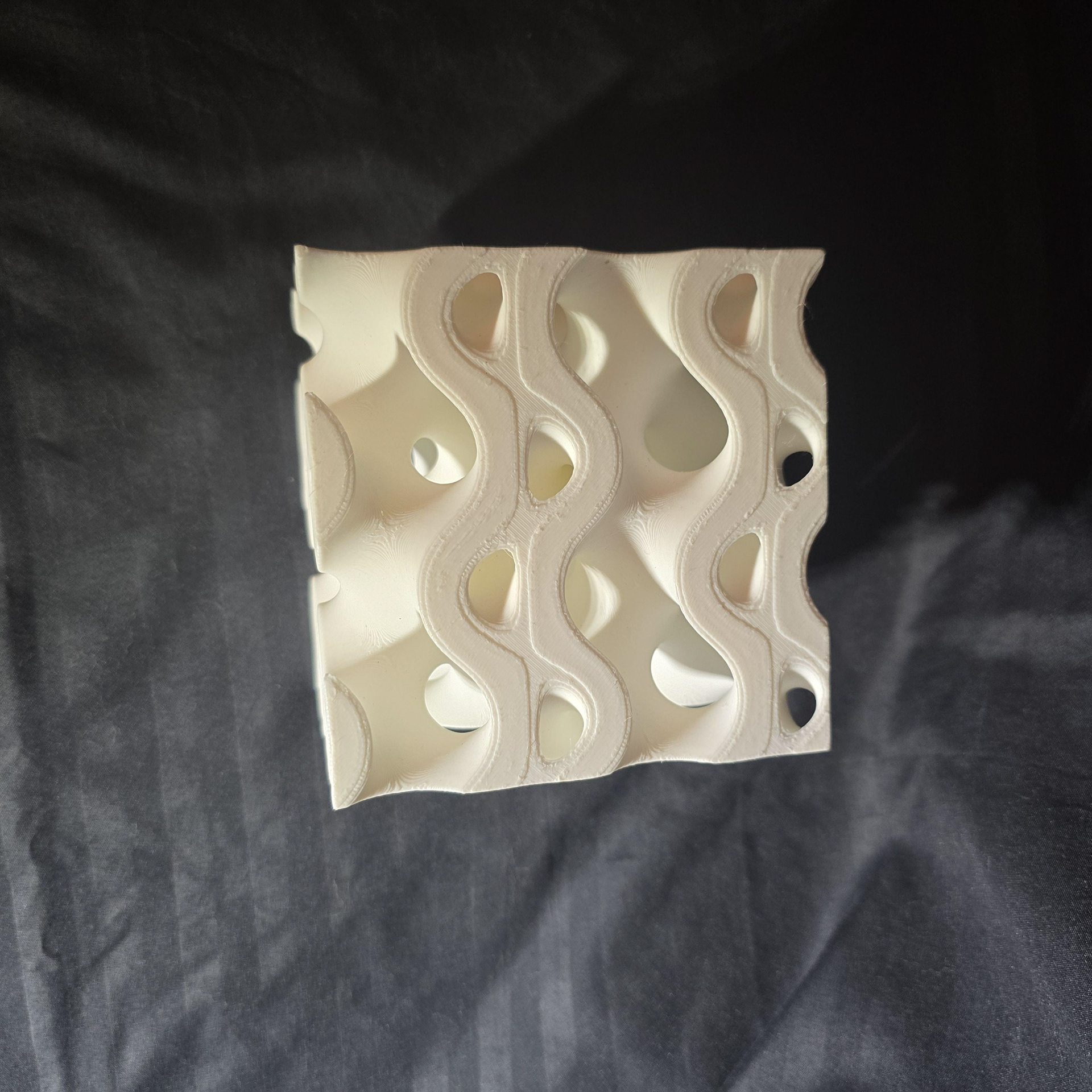
View into interior
This 100mm x 50mm x 25mm prototype was focused on testing the gyroid block structure as a way to distribute water with two distinct, non mixing pathways. The form is able to equally distribute liquid around blocks in the fluid path since all of one surface is continuous with itself.
Scale model for testing fluid seperation
View into interior of two channels
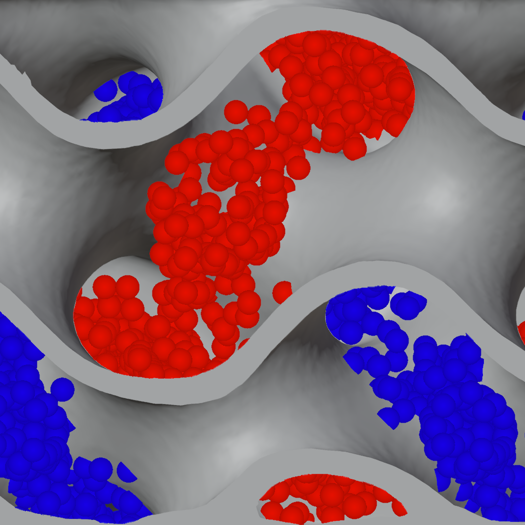
Top particle sim showing full separation at filling
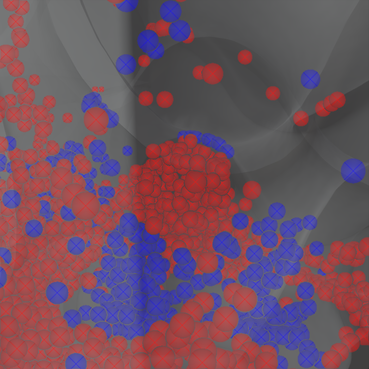
Channels remain distinct throughout form
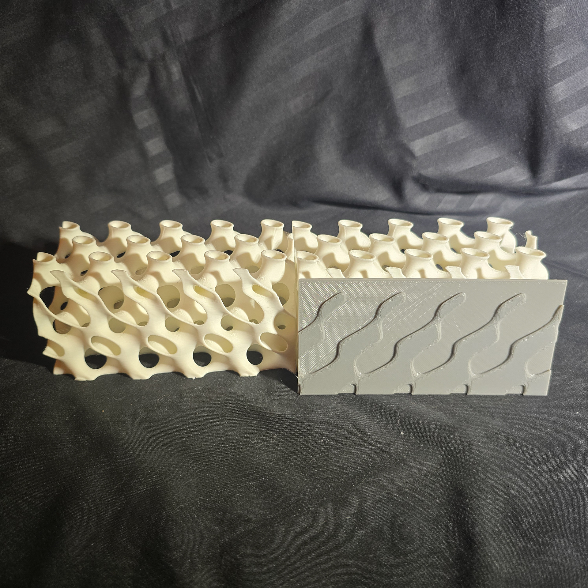
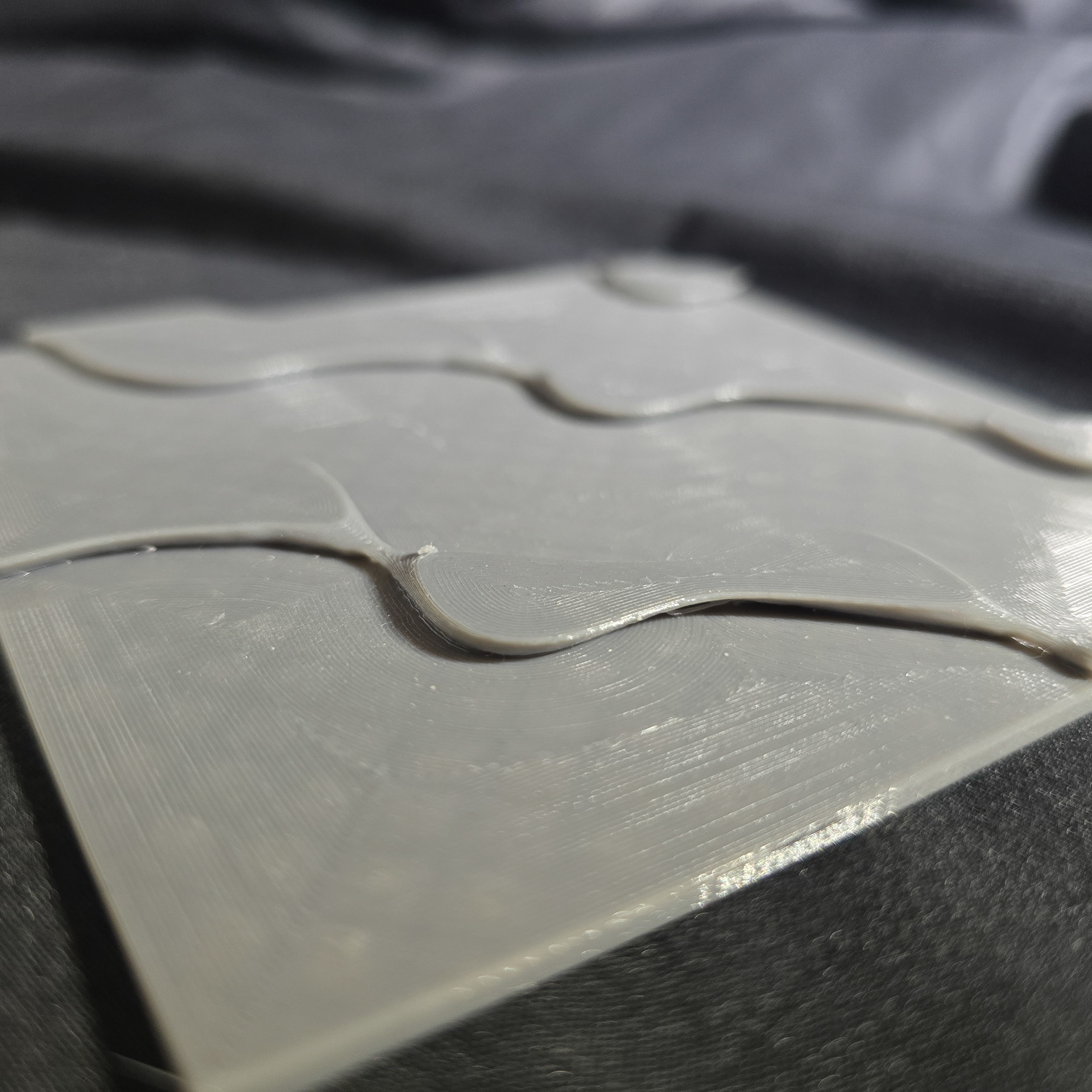
These 120mm x 60mm x 60mm prototypes were the first designed to not be completely enclosed and instead showcase the gyroid structure. This changed the focus of the design from taking advantage of two water channels to instead be about controlling the ratios between sides. In this iteration, water passes through only one channel, but that has been modified in order to better control the flow.
The field is a gyroid field with a scalar field modification, creating larger channels towards the top and front of the unit, with a 45 degree bias. This creates a offset grid for planting units to inset into, with smaller plantings taking advantage of the spacing between larger holes.
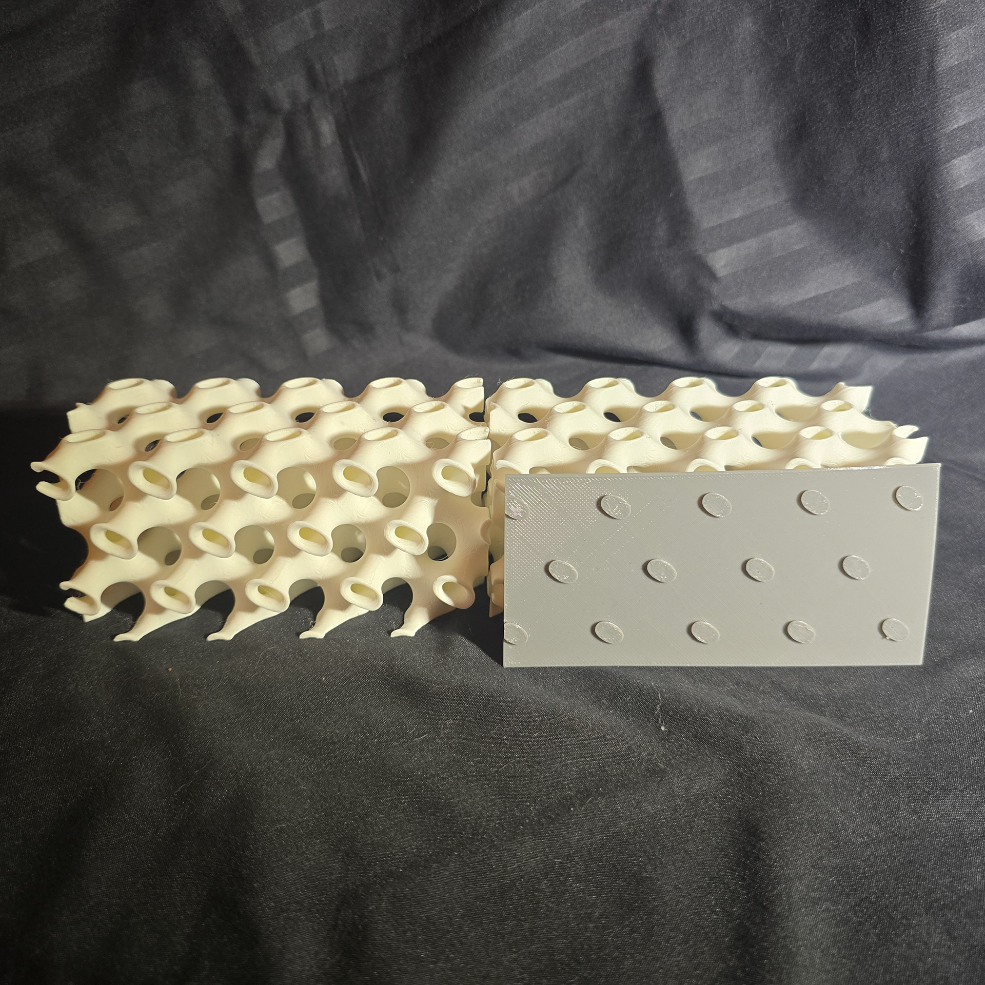
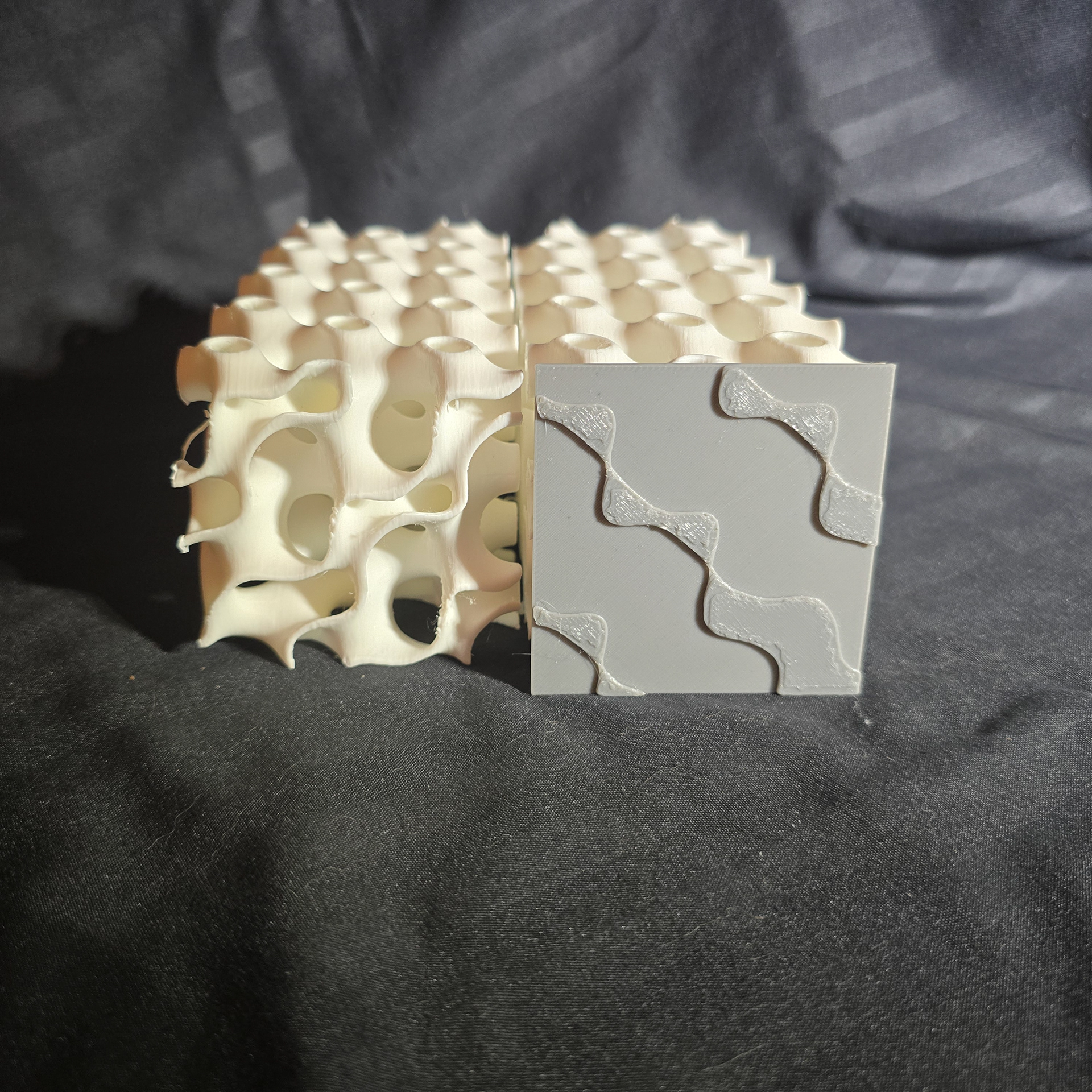
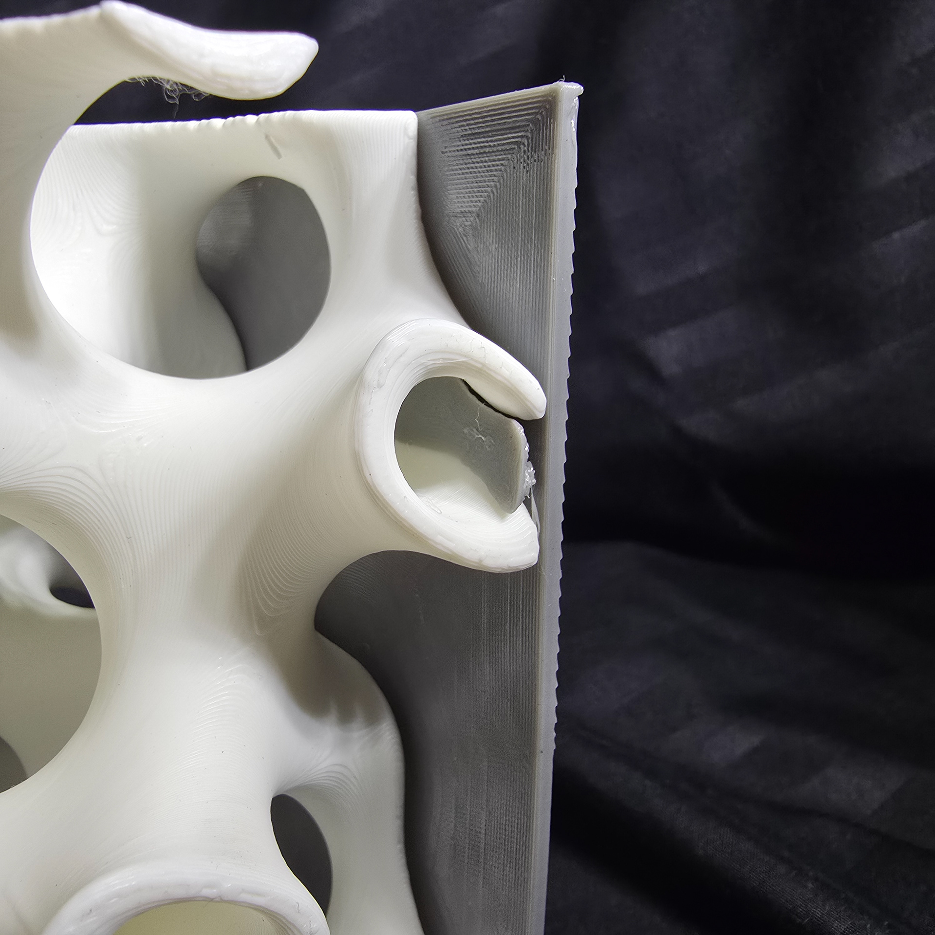
This is also the first iteration of flexible TPU cap plates for the faces of the gyroid, which were a moderate success. At this scale there was too little material to get a water tight fit except with the back face's small, regular holes. These were to eventually become mating gaskets to allow for water flow between gyroid blocks.
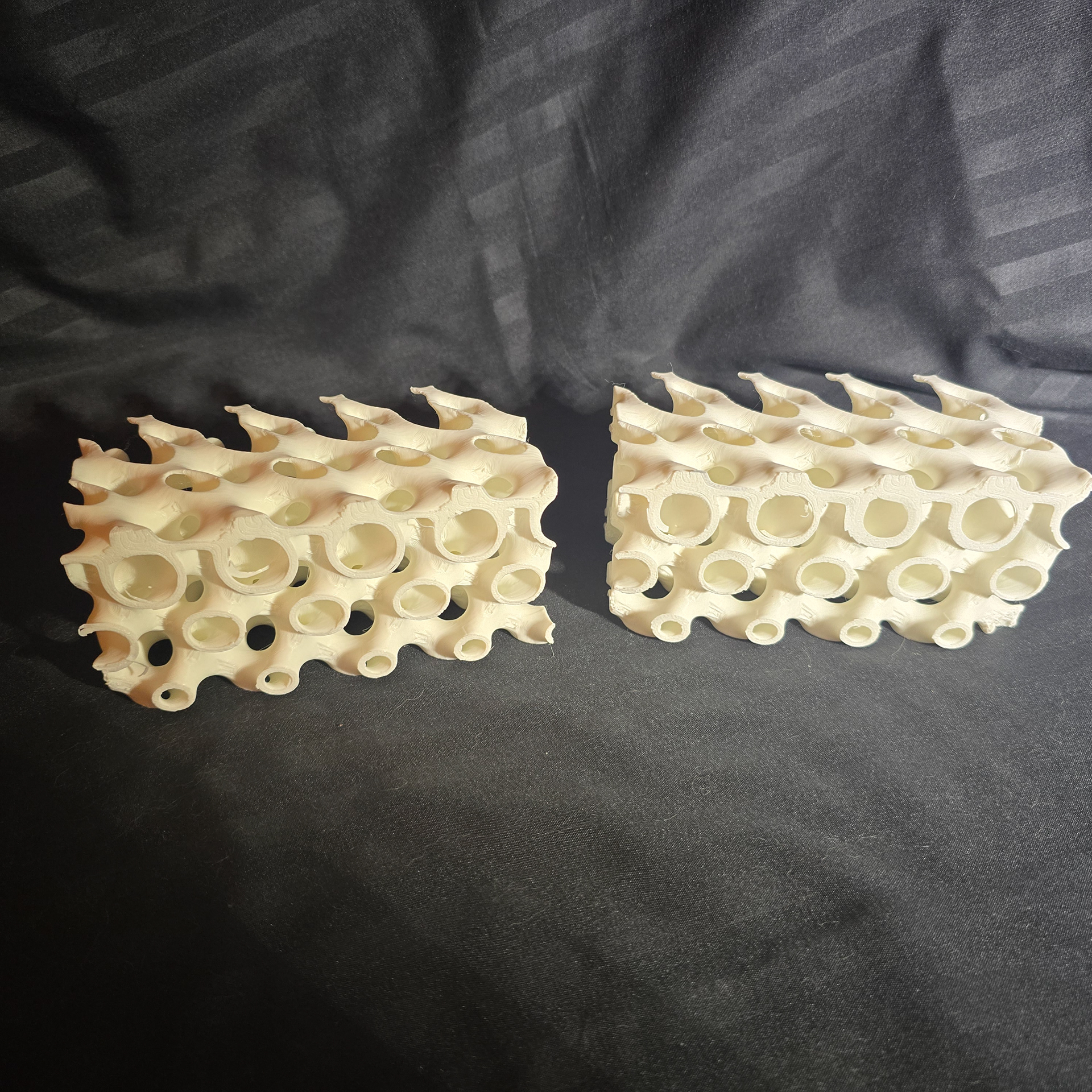
2 prototypes, showing front mating faces
Showing right/left mating faces
Showing top/bottom mating faces
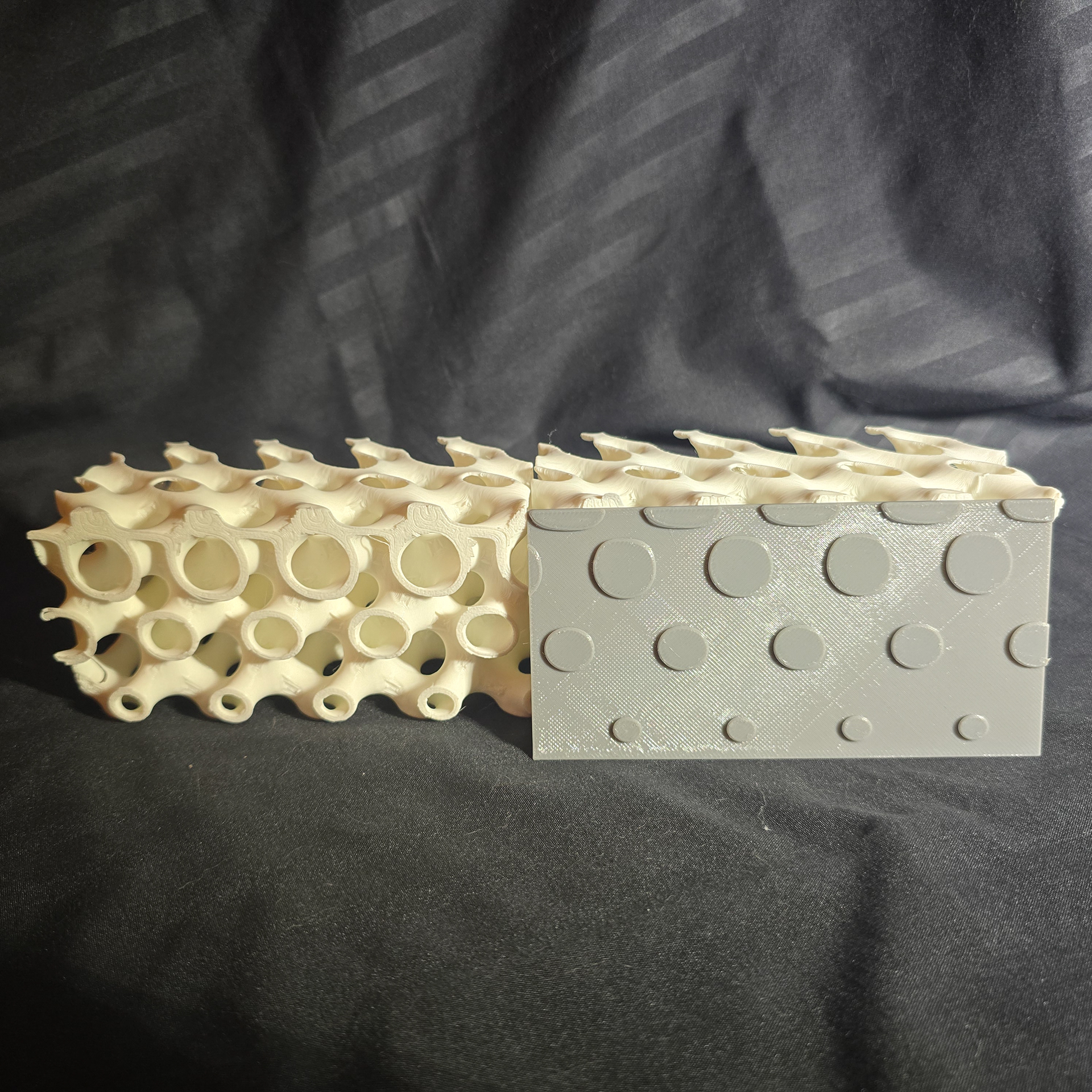
Front face with cap plate
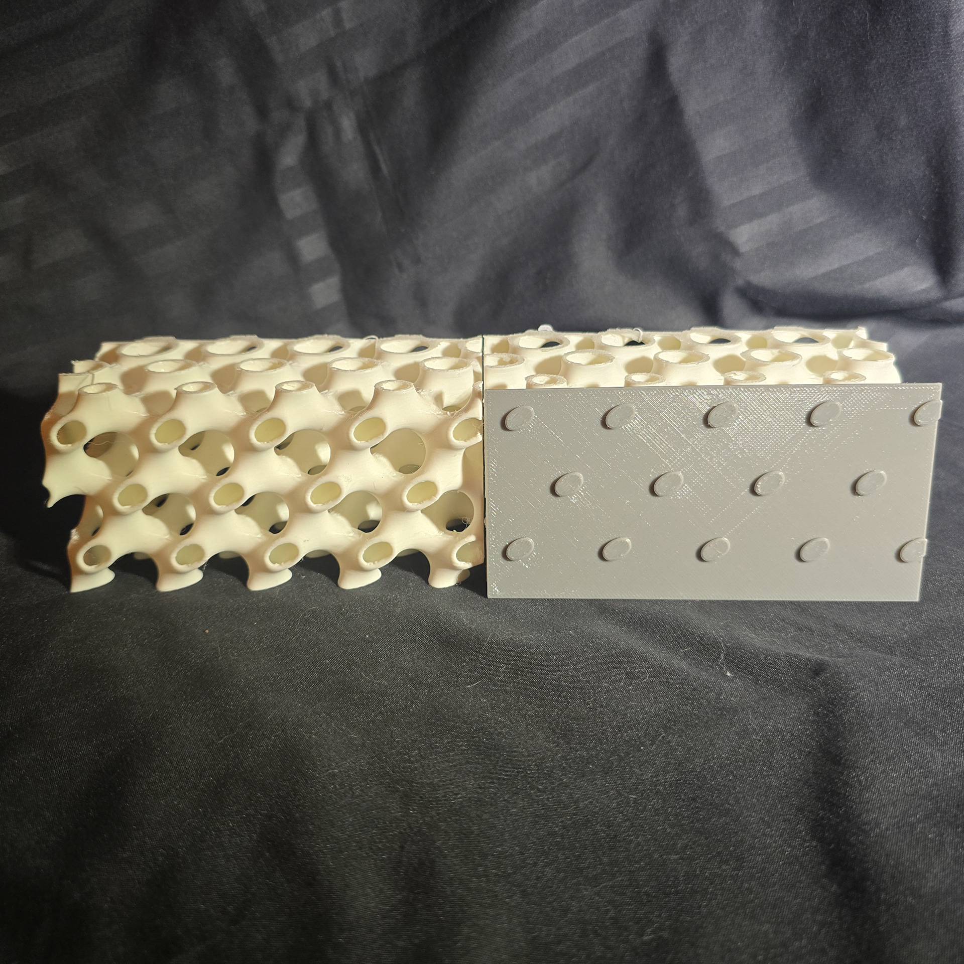
Rear face with cap plate
Top face with cap plate
Bottom face with cap plate
Right face with cap plate
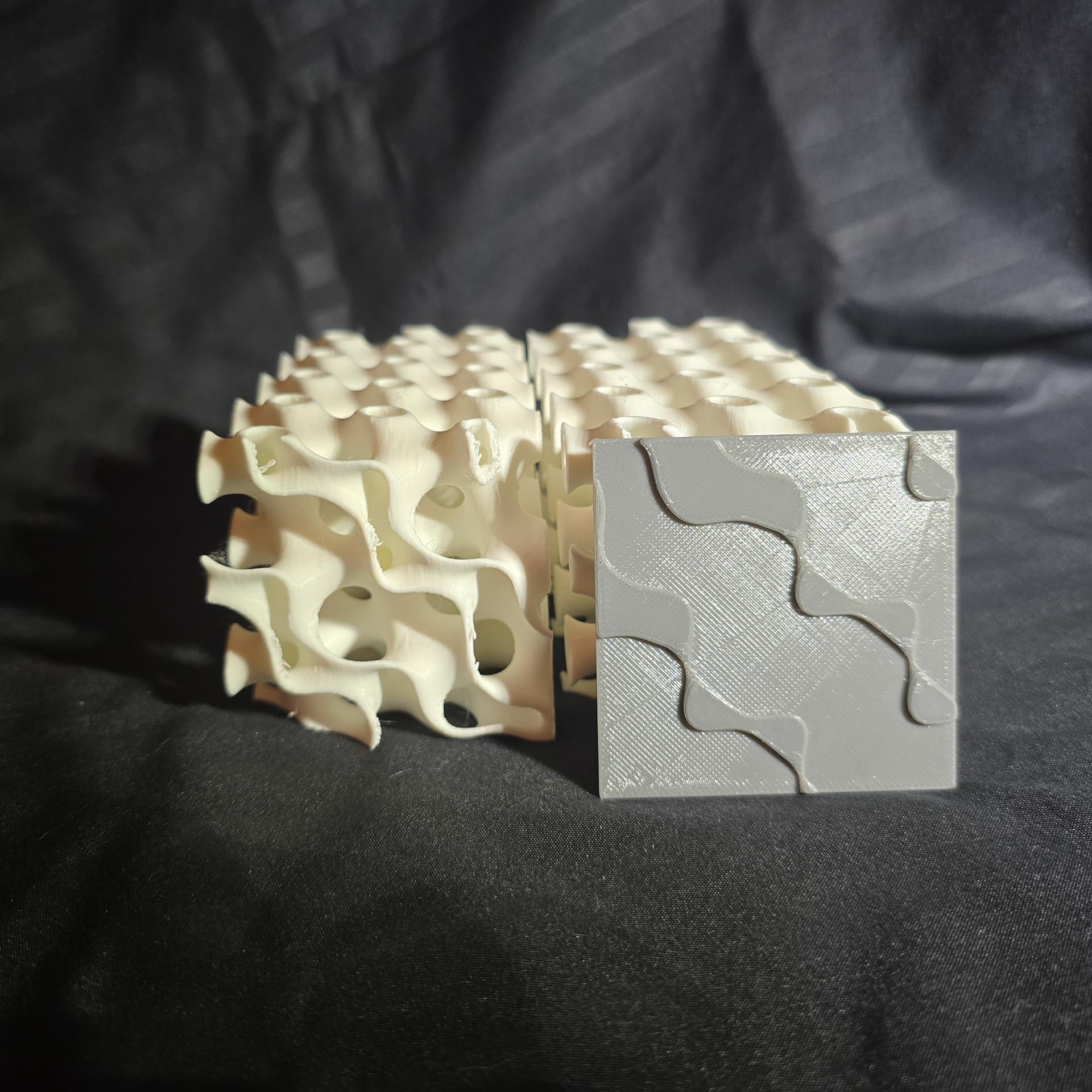
Left face with cap plate
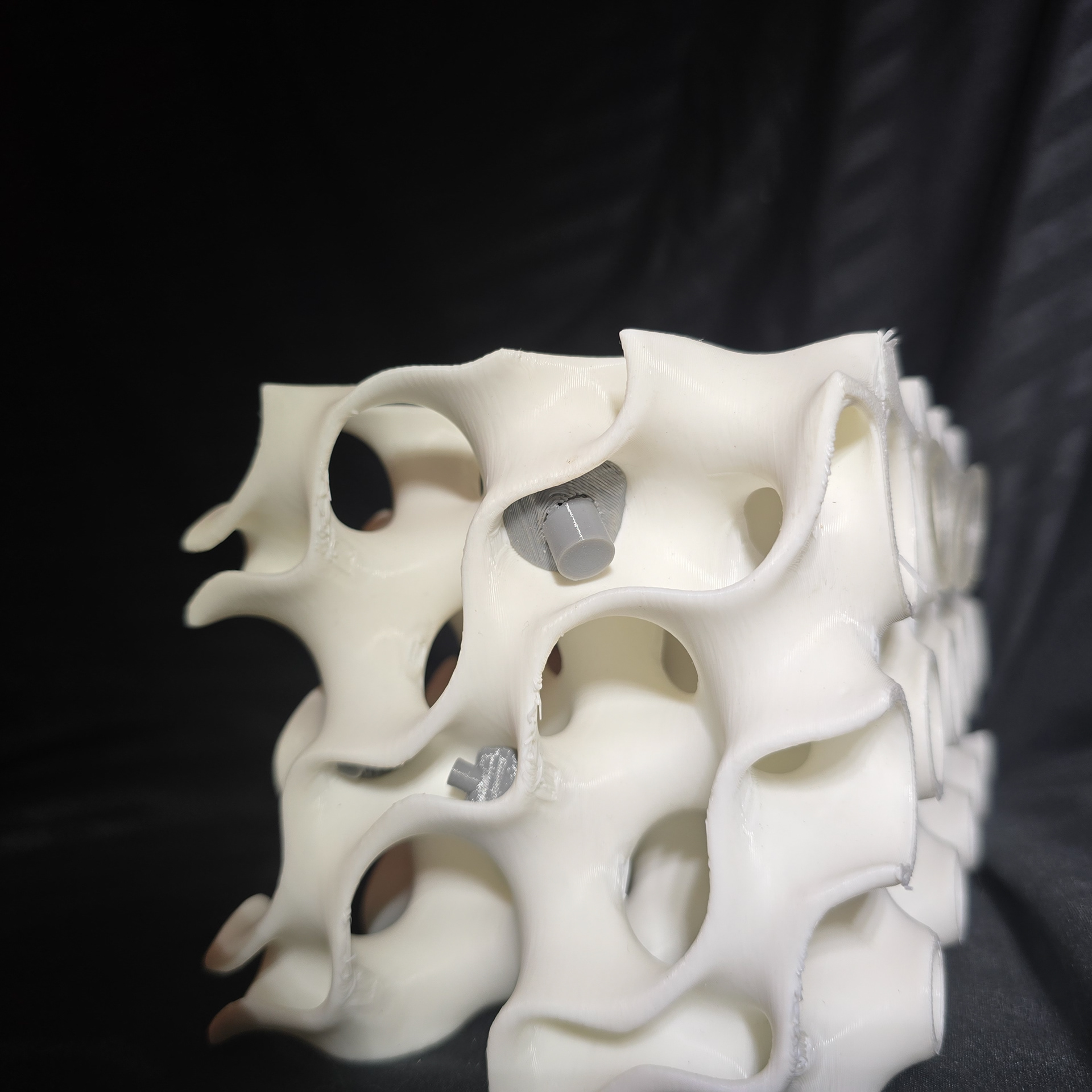
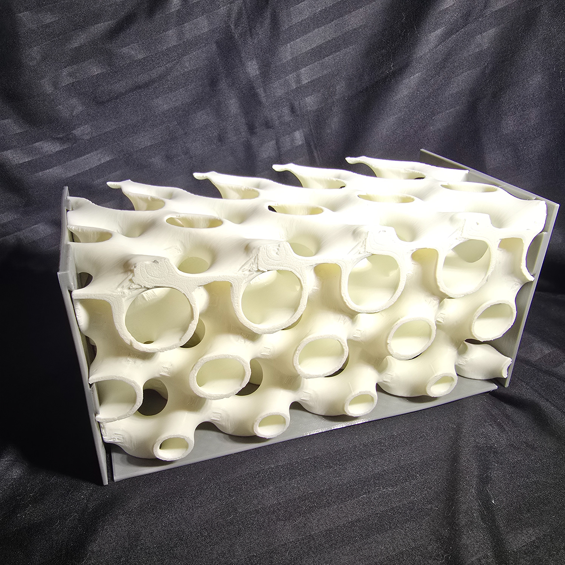
This is the largest prototype at 225mm x 112mm x 112mm, approximately 45% of the full 100cm x 50cm x 50cm design. This iteration features refinement in the scalar field modulation for more regularity, higher surface smoothness, and thinner walls that increase the volume of the water channels. Even using weaker PLA, with 3 printing walls and 10% infill this scale model easily supports over 75kg.
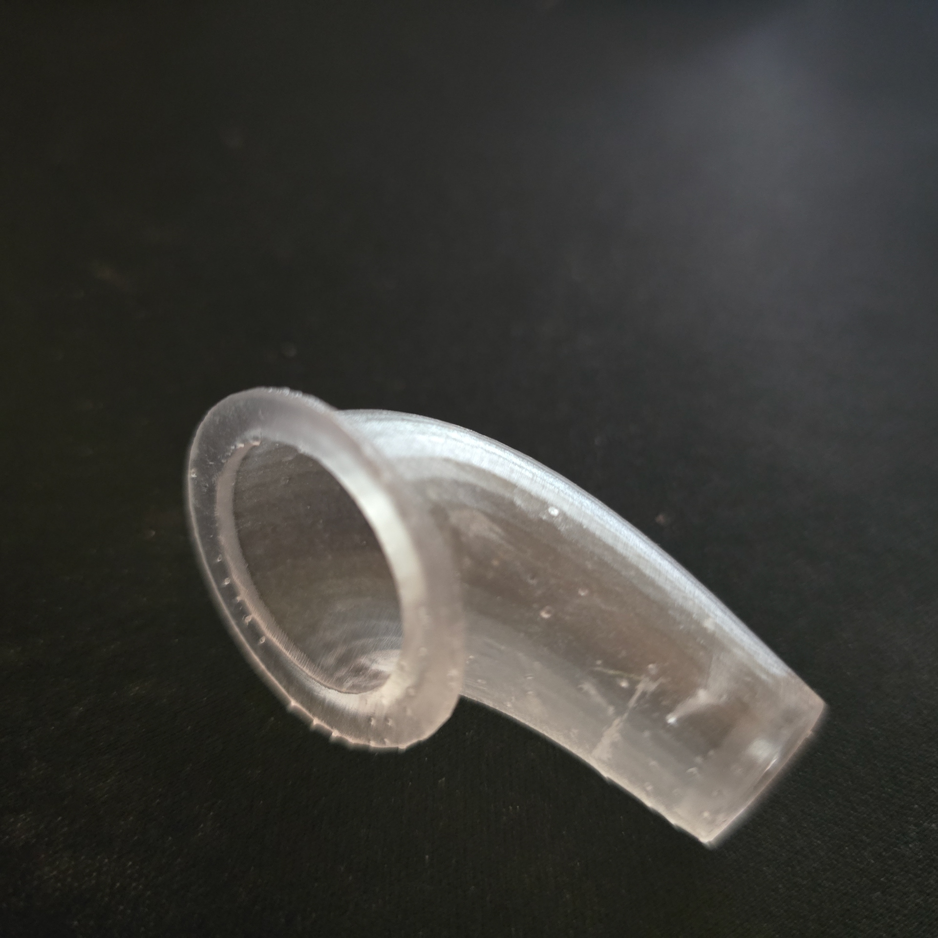
New, deeper versions of the cap plates were designed, but eventually abandoned in favor of individual plugs. The plugs are faster to print and use less material and instead interface directly with the deeper parts of the water channel. They provide a water tight fit even in the oddly shaped side channels now. They were created using mesh deformation between an icosphere and the gyroid surface, making perfectly snug caps. This process can also be used to create tubes to channel water between gyroid blocks.
With this model, I began also designing custom planting "cones" for the gyroid. Since the pattern is periodic between rows, only three unique cones are needed for this configuration and are easily adaptable. In their current form, they meet flush with the front face of the gyroid and curve down and to the left, tapering as it goes. In the next prototype, they will nest towards the rear of the gyroid block instead and will turn up to create a cup as it meets the block face.
Showing front of model with 3 inset resin planting cones
Close up showing increased depth of cap plate
Close up showing tight cap plate fitment
Showing gyroid with 3 cap plates affixed
Angled view into front large channel, showing tapering bias
Close up of new plug design in rear
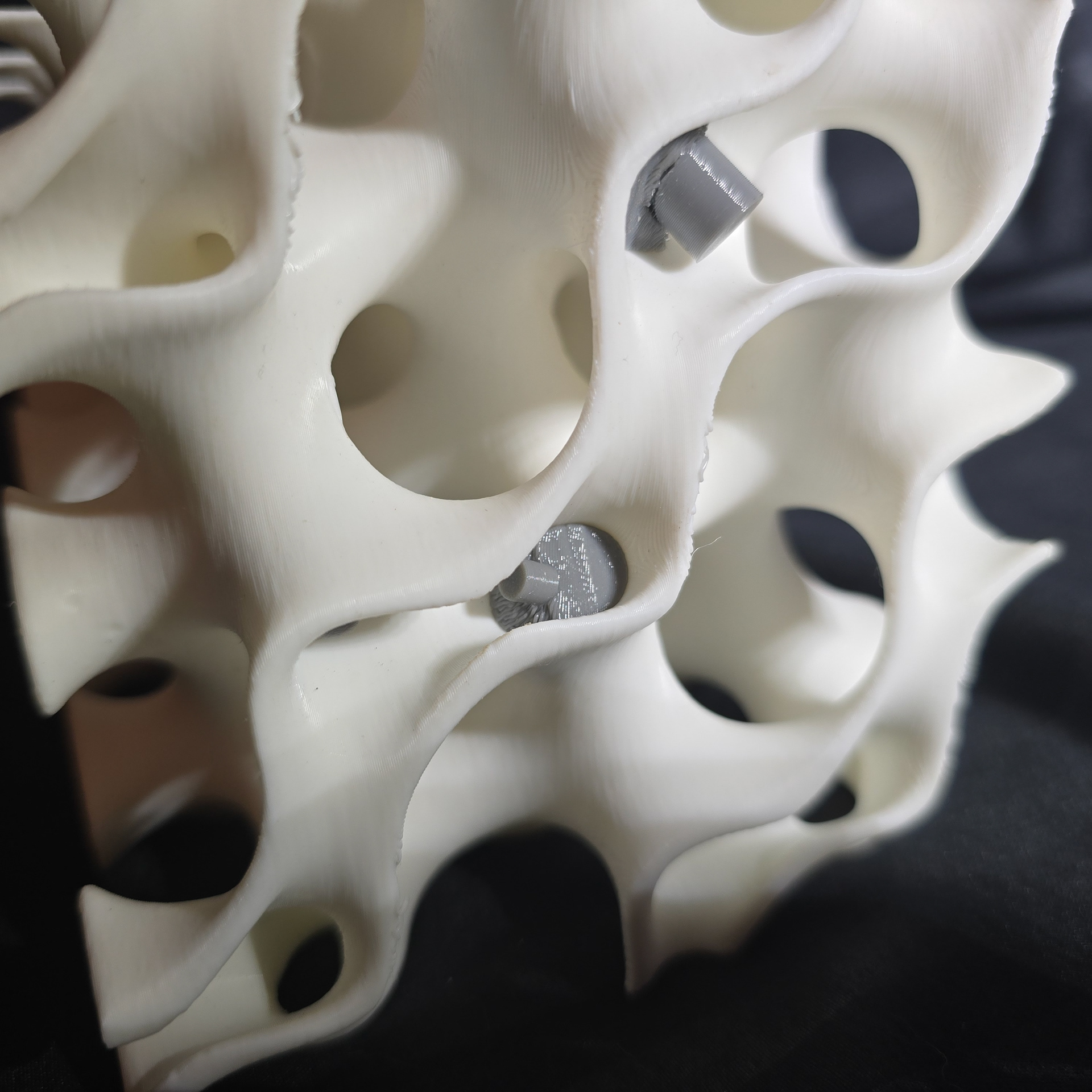
Close up of plugs in right side